Ground engineering and structural consolidation

Rock Injection

Polyurea-silicate resin injection can be used as part of an engineered rock-stabilisation and rock-support system. The process introduces a fast-reacting, high-strength material into accessible fractures, joints and void pathways, helping to bond discontinuous rock and improve the integrity of the treated zone.

Stabilisation and support

Structural bonding within accessible rock discontinuities

Rock injection is most effective where boreholes and packers can provide controlled access to connected fractures or open discontinuities. The two resin components are delivered separately and combined close to the point of injection. Once mixed, the resin reacts rapidly to form a dense, substantially non-expanding compound that bonds to the surrounding rock and bridges suitable pathways.

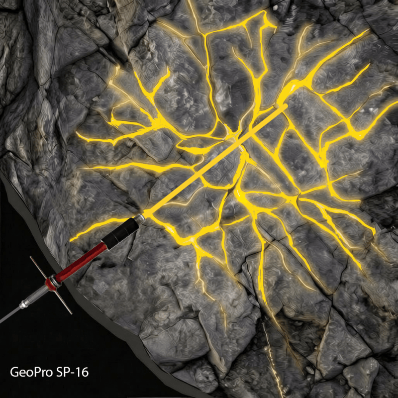
Diagram showing GeoPro SP-16 resin injected into fractures within rock
Illustrative resin injection into connected fractures and discontinuities within the rock mass.
01

Rock-mass consolidation

Resin can penetrate accessible fractures and joints, bonding loose or separated rock surfaces and improving continuity within the treated zone.

02

Excavation support

Injection may be undertaken ahead of, during or after excavation to support locally unstable ground and complement the designed support system.

03

Rapid strength development

Fast reaction can provide early bonding where treatment time is limited, provided the resin reaches the required pathways before its movement is restricted.

04

Controlled placement

Packers, pumps, mixer configuration and defined pressure and volume limits allow the treatment to be monitored and adjusted to the observed ground response.

GeoPro SP-16

Where SP-16 May Be Considered

GeoPro SP-16 is a low-viscosity, two-component polyurea-silicate resin intended for specialist injection applications where penetration, bonding and controlled consolidation are required. Final suitability must be confirmed through project-specific assessment, testing and design.

01

Rock-Mass Consolidation

May be considered for the treatment of fractured, jointed or locally weakened rock where low-viscosity penetration and structural bonding are required.

02

Fissure and Fracture Injection

May be used to penetrate connected fissures, joints and micro-voids, subject to aperture size, connectivity, pressure limitations and resin compatibility.

03

Loose or Disturbed Ground

May be considered for stabilising locally disturbed ground where controlled injection can improve continuity and reduce movement within the treated zone.

04

Tunnelling and Underground Works

May be incorporated into tunnelling or underground works for localised consolidation, pre-treatment and remediation, subject to the excavation method and ground conditions.

05

Groundwater-Related Treatment

May be considered where injection is required to improve the continuity of a ground-treatment zone. Water flow, pressure, resin reaction and environmental requirements must be assessed.

06

Settlement Mitigation

May be considered as part of a designed treatment strategy where voids, discontinuities or local ground weakness are contributing to settlement or movement.

Application guide · Injection methodology

Injection Technique

SP-16 is delivered through a controlled two-component injection system. The components remain separate through the pump and delivery hoses before combining in a suitable static mixer close to the packer and point of injection.

Injection arrangement

Controlled delivery into accessible rock pathways

Boreholes and packers provide access to the treatment zone. Resin is injected in a planned sequence while pressure, flow, volume and communication with nearby fractures or boreholes are monitored.

Injection control: Borehole spacing, injection sequence, pressure limits and target volumes should be established in the approved project method and adjusted where the observed ground response requires it.

Mixer selection

Match the mixer to the complete injection system

A static mixer repeatedly divides and recombines the two component streams. Its internal geometry, diameter and number of elements influence blending, flow resistance and the quantity of mixed resin retained in the assembly.

Mixer length considerations

Length is one part of mixer selection and should not be considered independently of performance.

Longer mixers

A longer mixing path may improve blending in some arrangements, but can also increase pressure loss and retained mixed volume.

Shorter mixers

A shorter assembly can reduce retained volume and replacement time, provided testing confirms homogeneous mixing under the intended operating conditions.

Configuration checks

  • Mixing performance: confirm that the geometry and element count produce a homogeneous mix.
  • Operating conditions: check performance at the intended ratio, temperature, viscosity and delivery rate.
  • Equipment compatibility: confirm the pressure ratings of the mixer, connections, hoses and packer.
  • Replacement: establish how a restricted mixer will be isolated, depressurised and safely changed.
Important: Do not shorten a mixer, remove elements or substitute another design unless the revised configuration has been verified for the resin and injection equipment.

Troubleshooting

Distinguish ground refusal from equipment restriction

Resin curing inside the mixer or lance can restrict flow and produce a pressure rise that resembles refusal, even though the treatment zone has not accepted the planned volume.

Possible sign Abrupt or premature pressure rise

The pressure response changes earlier or more rapidly than anticipated.

Possible cause Restricted mixer or lance

Partly cured resin has reduced the available flow path through the equipment.

Do not assess refusal from pressure alone. Compare pressure with flow, injected volume and the observed ground response. Isolate and depressurise the system before examining or replacing any component.

Between injections

Prevent mixed resin curing in the delivery path

Following an interruption or completed injection, mixed resin must be managed before it cures inside the mixer or lance. The approved method should define whether affected components are replaced or cleared.

A

Replace disposable components

Replace the mixer where it is designed for single-use operation or where flow has become restricted.

B

Use the specified clearing method

Flush only the permitted parts of the system and use only a medium approved for the resin and pump.

!

Confirm component-side flushing

Do not use the silicate component or another material as a flushing medium unless expressly permitted in the approved procedure.

Flushing materials and unmixed components should not be discharged into the ground unless their use forms an approved part of the injection method.

Operational sequence

Recommended injection workflow

  1. 1
    Prepare

    Confirm the resin, equipment, mixer and pressure ratings.

  2. 2
    Verify delivery

    Check component ratio, temperature, flow and mixer condition.

  3. 3
    Inject and monitor

    Track pressure, flow, volume and ground response.

  4. 4
    Respond

    Investigate unexpected pressure changes and manage interruptions safely.

  5. 5
    Complete the record

    Log locations, volumes, pressures, restrictions and actions taken.

Confirm the final mixer configuration, equipment limits, clearing method and acceptance criteria in the approved project procedure and current manufacturer documentation.

Injection Technique

Reducing Resin Escape During Rock Injection

Successful ground consolidation depends on keeping the mixed resin within the targeted joints and fractures until it has reacted sufficiently. This is especially important with silicate-modified polyurea systems, which generally produce little or no expansion and therefore cannot rely on foaming to fill open space. Effective containment is achieved by combining suitable resin characteristics with sealed injection points, controlled delivery and careful preparation of the components. Where the exposed rock is highly jointed, a temporary or permanent surface seal may also be required to prevent resin from escaping through interconnected fractures at the face.

1

Select Resin with a Fast Gel Time

The fast gel time of SP-16 helps control resin migration through open joints and connected fractures. After the components are mixed, the reaction develops rapidly and the resin begins to thicken, progressively reducing its ability to flow away from the intended treatment zone.

This short working time can improve resin retention, particularly where pathways lead towards an exposed face or where injection is undertaken in inclined or overhead boreholes. Injection pressure, delivery rate and sequence must therefore be carefully controlled so the resin reaches the required area before increasing viscosity restricts further movement.

2

Create a Secure Injection Point

Injection should take place through an appropriately sized mechanical packer or expanding lance positioned within the borehole. Introducing resin through an open, unsealed hole provides little control over the direction of travel and makes return flow more likely.

Expanding the packer against sound rock creates a firm seal behind the borehole collar. Pump pressure can then drive the resin into surrounding discontinuities rather than allowing it to follow the easier route back to the surface.

3

Provide a Surface Seal Where Required

Highly jointed or fractured rock may contain numerous pathways that extend directly to the exposed face. In these conditions, packers alone may not provide sufficient containment, as injected resin can escape through nearby joints before it has spread through the intended treatment zone.

Applying a suitable surface seal, such as shotcrete, helps close these openings and provides external confinement during injection. The shotcrete may be installed as a temporary sealing layer specifically for the injection works, or it may already form part of the permanent ground-support system.

The surface seal should develop adequate strength before injection begins. Its thickness, extent, condition and capacity to withstand the proposed injection pressure must be verified as part of the site-specific design.

4

Plan the Injection Order

For steep or vertical treatment areas, work will often advance from the lower injection points towards the upper points. The exact sequence should reflect the orientation of the joints, groundwater movement and the site-specific injection plan.

Beginning at a lower level can encourage trapped air and water to move towards designated relief points. Resin appearing at a neighbouring packer may indicate that a connected pathway has been reached, but uncontrolled discharge at the face should be sealed and assessed before injection continues.

5

Regulate Pressure and Quantity

Pump pressure, delivery rate and total resin consumption should be observed throughout each injection cycle. A gradual, controlled increase in pressure provides useful information about how the ground is accepting the material.

Applying too much pressure may open existing fractures, disturb weak rock or force resin through the face. Applying too little may leave the treatment incomplete. Where the equipment allows, measured batches can be programmed to reduce unnecessary pumping and help compare actual usage with the anticipated treatment volume.

6

Maintain Consistent Conditioning and Mixing

The two components must be delivered in the ratio stated by the resin manufacturer, commonly equal parts by volume. A suitable plural-component pump should feed both materials into an in-line static mixer capable of producing a consistent blend before the resin enters the packer.

Mixer dimensions should be selected for the particular resin, pump output and hose arrangement. Some installations use static mixers approximately 300–500 mm long, but length alone does not confirm adequate performance. Mixer design, internal element count, diameter and flow resistance must also be considered.

Poor proportioning or incomplete mixing can leave partially reacted material that remains fluid and escapes from the rock.

Technical Support

Need help assessing SP-16 for your rock injection project?

Speak with M&T Global about ground conditions, injection equipment and application requirements. Our team can help you determine whether GeoPro SP-16 is suitable for the proposed treatment.

Cookies preferences

✕

Others

Other uncategorized cookies are those that are being analyzed and have not been classified into a category as yet.

Necessary

Necessary
Necessary cookies are absolutely essential for the website to function properly. These cookies ensure basic functionalities and security features of the website, anonymously.

Advertisement

Advertisement cookies are used to provide visitors with relevant ads and marketing campaigns. These cookies track visitors across websites and collect information to provide customized ads.

Analytics

Analytical cookies are used to understand how visitors interact with the website. These cookies help provide information on metrics the number of visitors, bounce rate, traffic source, etc.

Functional

Functional cookies help to perform certain functionalities like sharing the content of the website on social media platforms, collect feedbacks, and other third-party features.

Performance

Performance cookies are used to understand and analyze the key performance indexes of the website which helps in delivering a better user experience for the visitors.